
It is one of the most common questions people ask before booking a thermal imaging inspection: can a thermal camera actually see electrical wires inside walls, ceilings, or conduit? The short answer is that a thermal camera cannot see through solid surfaces the way an X-ray does. Infrared radiation does not penetrate walls or conduit.
What a thermal camera does detect is heat. And because electrical wiring faults, overloaded circuits, loose connections, and degraded insulation all generate heat, a skilled thermographer can identify those faults indirectly, through the thermal signature they produce on the surfaces of panels, conduits, walls, and equipment.
1. How Thermal Cameras Work: The Physics Behind Infrared Detection
Every object with a temperature above absolute zero emits infrared radiation. The higher the temperature, the more infrared energy an object emits. A thermal camera, also called an infrared camera or thermographic camera, contains a sensor array that detects this infrared radiation and converts it into a visible image where different temperatures are displayed as different colours.
This is fundamentally different from visible light photography. A standard camera detects reflected visible light. A thermal camera detects emitted infrared energy. This distinction matters enormously for understanding what a thermal camera can and cannot do.
The infrared spectrum
Infrared radiation sits just below visible red light on the electromagnetic spectrum, at wavelengths between roughly 0.75 micrometres and 1,000 micrometres. Thermal cameras used for electrical and building inspections typically operate in the Long-Wave Infrared (LWIR) band, from approximately 8 to 14 micrometres. This band is well matched to the thermal emission of objects at room temperature and building temperatures, and it is the range in which most electrical faults produce their detectable signatures.
What a thermal camera actually measures
A thermal camera measures the surface temperature of whatever it is pointed at, specifically the apparent temperature of the outermost layer of the target surface. It does not measure internal temperatures. It does not see through surfaces. What it records is the thermal radiation leaving the outermost surface at the moment of measurement.
This is why emissivity settings matter so much for accurate readings. Emissivity is the ratio of the infrared radiation emitted by a real surface compared to a perfect theoretical emitter (a blackbody). A painted steel enclosure might have an emissivity of 0.95, close to a perfect emitter. A polished copper busbar might have an emissivity of 0.05, meaning it emits very little of its own radiation and instead reflects the infrared radiation of surrounding objects. Setting the wrong emissivity in a thermal camera produces temperature readings that can be dramatically incorrect.
Key point: A thermal camera sees surface temperature, not internal structure. It cannot see electrical wires themselves. What it can see is the heat those wires produce when they are overloaded, poorly connected, or failing, provided that heat is sufficient to raise the temperature of a detectable surface above its surroundings.
2. Can a Thermal Camera See Through Walls?
This is the most frequently misunderstood aspect of thermal imaging. The direct answer is no. A thermal camera cannot see through a solid wall in the way that an X-ray penetrates material. The infrared wavelengths used by LWIR thermal cameras do not pass through common building materials such as plasterboard, brick, concrete, timber framing, or insulation batts.
What a thermal camera can do, under the right conditions, is detect the thermal effect that something behind a wall produces on the surface of that wall. This is a completely different mechanism and it comes with significant limitations.
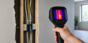
How heat from wiring conducts to a wall surface
When a wire inside a wall cavity is generating heat due to overloading, a poor connection, or insulation degradation, that heat conducts outward through the surrounding material. If the heat output is sufficient and the wall material is thin enough and thermally conductive enough, a temperature differential will eventually appear on the outer surface of the wall that a thermal camera can detect.
The key word is eventually. Heat conduction through building materials takes time and the temperature differential that reaches the outer surface may be very small, sometimes less than half a degree Celsius for a cable running inside a well-insulated cavity wall. Detecting this requires a high-sensitivity camera (Noise Equivalent Temperature Difference, or NETD, of 50 millikelvins or less), stable ambient conditions, and an experienced operator who can distinguish a genuine thermal anomaly from background variation.
Materials that block or transmit thermal radiation
Not all materials behave the same way with respect to thermal imaging. Understanding this helps set realistic expectations:
| Material | Thermal camera behaviour |
|---|---|
| Plasterboard (drywall) | Opaque to LWIR infrared. Camera sees only the plasterboard surface temperature. Internal wires are not visible as objects, only as heat conducting to the surface. |
| Brick and concrete | Opaque to infrared. High thermal mass means heat from wiring conducts very slowly to the surface. Anomalies may take hours to appear and are often very small. |
| Glass (standard) | Standard glass is largely opaque to LWIR infrared. A thermal camera pointed at a window sees the glass surface temperature, not what is behind it. |
| Thin plastic conduit | Partially transmissive to LWIR in very thin sections, but generally treated as opaque. The outer surface temperature of a conduit carrying an overloaded cable will be elevated. |
| Metal conduit or trunking | Opaque to infrared, but metal conducts heat very efficiently. An overloaded cable inside steel conduit will raise the conduit surface temperature noticeably. |
| Insulation batts (in cavity walls) | Acts as a thermal barrier. Insulation significantly slows the conduction of heat to the wall surface, making detection of cable faults in insulated cavities much harder. |
| Air gap (uninsulated cavity wall) | Air is a poor conductor. Heat from wiring must radiate and convect across the cavity before conducting through the inner leaf of the wall. Detection is possible but requires significant heat output from the fault. |
3. What Thermal Cameras Do Detect in Electrical Systems
While a thermal camera cannot see the physical form of a wire inside a wall, it is an exceptionally powerful tool for detecting electrical faults, and the reason comes back to physics. Electrical faults generate heat. That heat has to go somewhere. And in many common scenarios, the heat output is significant enough to produce a clear, detectable temperature differential on accessible surfaces.
The scenarios where thermal imaging reliably and clearly detects electrical problems are the ones where the heat source is either exposed or is in close thermal contact with a surface the camera can see directly. This covers the vast majority of real-world electrical fault detection.
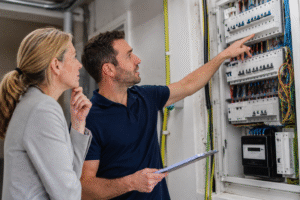
Switchboards and distribution boards
This is where thermal imaging delivers its greatest value in electrical safety work. Inside a switchboard, connections, busbars, circuit breakers, and cable terminations are all exposed or in close proximity to each other. A loose connection, a corroded terminal, or an overloaded breaker generates heat that is immediately visible to a thermal camera with no need to conduct through any barrier.
Under AS ISO 18434-1:2023, temperature rise above ambient (delta T) is used to classify severity. A 10 to 20 degree Celsius rise above an equivalent component under similar load may indicate a developing fault. A rise above 40 degrees Celsius in a connection is typically classified as critical under Australian and international thermography practice.
Our thermal imaging services focus heavily on switchboard and distribution board surveys because this is where electrical fires originate in Australian commercial and industrial premises.
Cable trays and open wiring runs
Where cables run in open trays, on exposed cable ladders, or through areas without enclosures, a thermal camera can scan directly across the cable surface. An overloaded cable, a cable running at or above its rated current-carrying capacity, or a cable with compromised insulation will show elevated surface temperature relative to adjacent cables carrying normal loads.
This is particularly useful in industrial settings such as factories, data centres, and warehouses where large numbers of cables run in exposed trays and individual circuit loading can change significantly over time as production equipment is added or reconfigured.
Motor control centres and VSD panels
Variable speed drives, motor starters, contactors, and overload relays are all sources of electrical heat and all potential failure points. Thermal imaging of a motor control centre can identify a failing contactor before it causes a production shutdown, a VSD running at elevated internal temperature due to inadequate ventilation, or a motor winding drawing excess current due to a developing mechanical fault.
Underground and in-wall cables: the partial picture
For cables buried in walls, floors, or underground, the picture is more complex. As described in Section 2, a thermal camera may detect the surface thermal signature of a seriously degraded cable in some circumstances. However, this is not reliable enough to be used as a primary detection method for in-wall wiring faults.
In practice, thermal imaging of wall surfaces is most useful for two specific scenarios: detecting cable routes (by the very slight warming caused by current flow, in lightly insulated or uninsulated cavities) and identifying areas of suspected overheating for follow-up investigation. It does not replace cable fault location tools such as time-domain reflectometers or insulation resistance testing for in-wall faults.
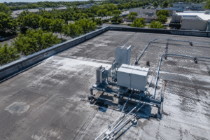
Solar PV installations
Thermal imaging is a well-established tool for inspecting solar photovoltaic arrays under IEC 62446-3, which is used as guidance in Australia. On a PV panel, bypass diode failures, cell delamination, soiling patterns, and string wiring faults all produce characteristic thermal signatures visible from the front surface of the panel under solar irradiance. A certified thermographer can identify underperforming strings, hot cells, and connection faults from a scan of the panel surface.
4. Thermal Camera Detection: Scenario by Scenario
The following table summarises what a thermal camera can and cannot detect across the most common electrical inspection scenarios in Australian buildings and facilities.
| Scenario | What the camera detects | Limiting factor | Verdict |
|---|---|---|---|
| Switchboard connections and busbars | Hot spots from loose connections, overloaded circuits, failing breakers | Load must be at least 40% of rated capacity for meaningful readings | Highly reliable. Core application for thermal imaging in electrical safety. |
| Open cable tray runs (exposed) | Overloaded cables, cables exceeding current-carrying capacity | Adjacent cables must be under comparable load for relative comparison | Reliable for identifying overloaded circuits and cable sizing issues. |
| Cables inside steel conduit (surface) | Elevated conduit surface temperature from overloaded cable inside | Requires significant overloading; small anomalies may not show clearly | Useful as a secondary check. Not a substitute for insulation resistance testing. |
| Cables inside plastic conduit (surface) | Moderate surface heating from overloaded or deteriorating cable | Detection less reliable than steel conduit due to lower thermal conductivity | Conditional. Depends on load level and ambient temperature stability. |
| Cables in uninsulated cavity walls | Very slight surface warming of wall surface above cable route | Requires high sensitivity camera and experienced operator; marginal faults will not show | Limited. Useful for fault location only if heating is significant. |
| Cables in insulated cavity walls | Rarely detectable; insulation blocks heat conduction to wall surface | Insulation acts as a thermal barrier; only serious faults may produce a signature | Not reliable. Other testing methods should be used for in-wall cables. |
| Cables in concrete slab or underground | Not detectable under normal conditions | Concrete thermal mass prevents any surface signature from low-level faults | Not applicable. Use cable fault location instruments instead. |
| Solar PV panels (from front surface) | Hot cells, bypass diode failures, soiling, string faults | Requires adequate solar irradiance (at least 700 W/m2) for reliable results | Highly reliable under correct conditions. Standard practice per IEC 62446-3. |
| Motor control centres and VSDs | Failing contactors, overloaded motors, inadequate cooling | Equipment must be under normal operating load at time of inspection | Very reliable. High value for predictive maintenance in industrial settings. |
| Overhead service entry cables (exposed) | Cable overheating from overloading or damaged insulation on outer sheath | Only outer sheath surface visible; internal conductor temperature inferred | Useful for identifying seriously overloaded service cables. |
5. The Conditions Required for Accurate Thermal Detection of Wiring Faults
Even in the scenarios where thermal imaging can detect wiring faults, the results depend heavily on the conditions at the time of the inspection. This is one of the most important reasons why a hired camera in untrained hands produces unreliable results compared to a certified professional operating under a structured methodology.
Adequate load at time of inspection
Under AS ISO 18434-1:2023, electrical thermal inspections should be conducted with the installation carrying at least 40 percent of its rated load. Below this threshold, the temperature rise in a faulty connection or overloaded cable may be too small to differentiate from normal variation. In Australian commercial buildings, off-peak surveys conducted at night or on weekends often fail this criterion, which is why professional thermographers confirm load conditions before scanning and document them in the report.
Stable ambient conditions
Thermal cameras are highly sensitive to ambient temperature changes. Drafts from air conditioning or ventilation, direct sunlight through windows, and recently changed load conditions all introduce thermal noise that can obscure genuine fault signatures or create false anomalies. A professional operator allows the installation to stabilise under load before scanning and documents ambient conditions in the report.
Emissivity settings matched to materials
As mentioned in Section 1, emissivity has a direct and significant effect on measured temperatures. Professional thermographers adjust emissivity for each material type during a survey. Most rental cameras default to an emissivity of 0.95, which produces accurate readings for painted or coated surfaces but serious errors for bare metal components. This is not a minor calibration detail. Setting emissivity incorrectly on a polished copper busbar (true emissivity approximately 0.05) at a default of 0.95 will produce temperature readings that are wrong by tens of degrees Celsius.
Camera sensitivity (NETD)
For electrical and building inspection work, the camera’s Noise Equivalent Temperature Difference (NETD) should be 50 millikelvins or less. This is the smallest temperature difference the camera can reliably detect. Cameras with higher NETD values, which includes many entry-level and mid-range hire cameras, will miss subtle thermal anomalies that a professional-grade camera would capture. For switchboard work this is less critical, because the temperature differentials are usually large. For in-wall cable detection, high sensitivity is essential.
Correct inspection geometry
Every thermal camera has a minimum distance-to-spot ratio: the minimum distance at which the camera can produce a reliable temperature measurement for an object of a given size. Operating too close to a target reduces measurement accuracy. For electrical work on switchboard components, the camera should be at an appropriate distance and angle to capture the full extent of the target without distortion from the viewing angle. Angles greater than 45 degrees from perpendicular introduce significant emissivity errors.
6. What Thermal Imaging Cannot Do in Electrical Inspections
Understanding the limitations of thermal imaging is just as important as understanding its capabilities. A professional thermographer will be straightforward about these limits. Any provider who claims that thermal imaging can see all wiring inside walls or find all electrical faults should be questioned carefully.
It cannot see through insulated walls reliably
As detailed in Section 2 and Section 4, a thermal camera does not penetrate insulated wall cavities with sufficient sensitivity to detect borderline cable faults. A badly overloaded cable in an insulated wall may show a very faint surface signature, but a cable running at or slightly above its rated current, which is exactly the scenario most likely to cause a fire over time, will not produce a detectable surface signature through 90mm of insulation batts.
It cannot identify the specific cause of a hot spot
A thermal camera identifies that a temperature anomaly exists and approximately where it is. It does not identify the specific cause. A hot circuit breaker terminal might indicate a loose connection, a corroded terminal, an overloaded circuit, or a failing breaker. The thermographer can narrow down the likely cause based on the thermal pattern and context, but confirmation requires follow-up investigation by a licensed electrical worker. Thermal imaging is a screening and prioritisation tool, not a final diagnosis tool.
It cannot replace insulation resistance testing
Degraded insulation does not always produce heat. A cable with compromised insulation that is not carrying high current may fail an insulation resistance test at 500V DC while showing no detectable thermal anomaly under normal operating conditions. The insulation resistance test under AS/NZS 3760:2022 and AS/NZS 3000:2018 clause 8.3.2 is a direct measurement of insulation condition. Thermal imaging is not a substitute for it.
It cannot see static or de-energised faults
A thermal camera only detects faults that are actively generating heat at the time of the inspection. A circuit breaker with a corroded terminal that is not currently under load, or a cable with compromised insulation that has not yet failed, will not show a thermal anomaly. This is why thermal imaging inspections must be conducted under load and why they complement rather than replace periodic electrical testing under AS/NZS 3017:2022.
It cannot provide a legally compliant inspection record on its own
A set of thermal images without a structured report, severity classification, load conditions, emissivity data, thermographer certification details, and remediation recommendations does not constitute a compliant thermographic inspection report under AS ISO 18434-1:2023. Insurers, WHS inspectors, and safety auditors in Australia require the full documented report, not just the images. This is a critical distinction for any business relying on thermal imaging for compliance purposes.
7. Practical Applications: Where Thermal Imaging Adds Real Value in Australian Electrical Safety
With a clear picture of what thermal imaging can and cannot do, the practical question becomes: where does it add genuine value in the Australian electrical safety context? The answer is specific and useful.
Annual switchboard surveys for commercial and industrial properties
This is the primary high-value application. Australian commercial and industrial switchboards carry dozens to hundreds of terminations, any one of which can develop a loose connection over time due to vibration, thermal cycling, corrosion, or initial installation quality. A thermal survey of a switchboard under load finds these hot spots quickly and non-invasively, without the need to shut down the supply or expose live parts.
Many Australian commercial property insurers now require documented annual thermal surveys as a condition of electrical and business interruption cover. Our electrical safety inspections incorporate thermal imaging as a standard component of comprehensive facility electrical audits.
Preventive maintenance programmes for manufacturing and industrial sites
In factories and industrial facilities, thermal imaging of motor control centres, VSD panels, transformer terminations, and busbar systems forms part of a condition-based maintenance programme. Identifying a failing contactor before it causes an unplanned shutdown or a busbar joint running hot before it causes a busbar failure can save significant production losses and equipment replacement costs.
Combined with our energy optimisation services, a thermal survey of major plant equipment can identify both safety risks and energy waste from high-resistance connections and inefficient motor operation at the same time.
Post-installation verification
After a major electrical installation or upgrade, a thermal survey under load provides a rapid check that all connections have been correctly made and that no circuits are running unexpectedly hot. It is particularly valuable after switchboard upgrades, main cable replacements, or the addition of significant new load.
Building condition assessments and pre-purchase electrical inspections
For older commercial buildings and strata complexes, a thermal survey of the main switchboard and distribution boards provides a snapshot of the electrical health of the installation that a visual inspection alone cannot match. It is a useful component of pre-purchase due diligence for commercial properties.
Insurance and WHS compliance documentation
An AS ISO 18434-1:2023 compliant thermal inspection report provides documented evidence that the PCBU has taken reasonable steps to identify electrical risks, as required under the Work Health and Safety Act 2011 (Cth). When combined with a remediation record showing that identified faults were rectified, this creates the kind of defensible compliance trail that protects businesses in the event of an incident or insurance claim.
8. DIY Thermal Imaging vs Professional Inspection for Electrical Wiring
Given the physics involved, what is the practical difference between a property owner using a hired thermal camera to check their wiring versus engaging a certified professional?
For the scenarios where thermal imaging is most reliable, specifically switchboard inspection and exposed cable runs, the main limitations of a DIY approach are operator skill, emissivity configuration, load condition verification, and the absence of a compliant report. A hired camera pointed at a switchboard will show thermal images. Whether those images are being interpreted correctly, whether the emissivity is set appropriately for each component, and whether the load conditions at the time of the scan are adequate for meaningful results depends entirely on the operator’s knowledge.
For the scenarios where thermal imaging has inherent limitations, specifically in-wall and in-conduit cable detection, neither a professional nor a DIY operator can reliably detect borderline faults through insulated cavities. The physics applies equally regardless of who is holding the camera. The professional advantage here is knowing when to say the thermal method is not appropriate and recommending the correct alternative test.
The honest summary: A thermal camera in competent hands is a powerful and genuinely useful electrical safety tool. The same camera in untrained hands, without correct configuration, without load verification, and without a structured reporting methodology, produces images that may look convincing but cannot be relied upon for safety or compliance decisions. The camera is not the variable that determines the outcome.
Frequently Asked Questions
Can a thermal camera find wiring behind plasterboard walls?
In some circumstances, yes. If the wiring is generating significant heat due to overloading or a fault, and the wall has low thermal resistance (uninsulated cavity, thin plasterboard directly over the cable), a sensitive thermal camera may detect a surface temperature differential. In insulated modern walls, borderline faults will not produce a detectable surface signature. Thermal imaging is not a reliable method for locating or inspecting cables that are embedded in insulated walls.
Can thermal imaging replace electrical testing for wiring?
No. Thermal imaging complements electrical testing but does not replace it. Tests such as insulation resistance testing (AS/NZS 3760:2022 and AS/NZS 3000:2018), earth continuity testing, and earth fault loop impedance testing check specific electrical properties of wiring that a thermal camera cannot measure. The two approaches identify different types of faults and are both needed for comprehensive electrical safety compliance.
Why does a thermal camera not work through walls?
Thermal cameras detect infrared radiation emitted from surfaces. Infrared radiation in the LWIR band (8 to 14 micrometres) does not pass through solid materials such as plasterboard, brick, or concrete the way radio waves or X-rays do. The camera can only detect the surface temperature of whatever material it is aimed at. Heat from wiring behind a wall must conduct through the wall material and raise the outer surface temperature before the camera can detect it.
What temperature difference can a thermal camera detect?
Professional-grade thermal cameras used for electrical inspections have a Noise Equivalent Temperature Difference (NETD) of 50 millikelvins (0.05 degrees Celsius) or less. This means they can reliably detect temperature differences as small as a tenth of a degree Celsius under good conditions. In practice, ambient variation, emissivity errors, and reflected radiation mean that reliable anomaly detection in building inspection scenarios typically requires a differential of at least 0.5 to 1.0 degrees Celsius on the surface being scanned.
Is thermal imaging useful for checking if wiring is overloaded?
Yes, for accessible wiring. Cables running in open trays, conduits with accessible surfaces, and exposed distribution board cables can all be checked for overloading using thermal imaging. An overloaded cable runs hotter than a cable at normal load and this temperature differential is visible on the cable or conduit surface. For cables inside insulated walls or buried underground, overloading may not produce a detectable surface signature.
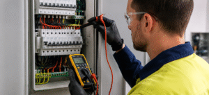
Who can conduct a thermal imaging inspection for electrical purposes in Australia?
For a compliant thermographic inspection under AS ISO 18434-1:2023, the operator should hold at minimum an AINDT (Australian Institute for Non-Destructive Testing) Level II Infrared Thermography certification, or ASNT equivalent. For electrical thermal surveys specifically, the thermographer should also be, or work alongside, a licensed electrical worker who can correctly interpret findings in the context of the installation. All compliant reports must include the thermographer’s certification details.
Can thermal imaging detect underground cable faults?
Not reliably in normal conditions. Underground cables are surrounded by significant thermal mass (soil, concrete, backfill) that absorbs heat and prevents any meaningful surface temperature signature from reaching a level detectable by a thermal camera. Cable fault location for underground cables is typically performed using time-domain reflectometry (TDR) or similar specialist cable fault finding equipment. Thermal imaging is not the appropriate tool for underground cable fault detection.
The Bottom Line
A thermal camera cannot see electrical wires in the way an X-ray sees through material. What it can do is detect the heat that electrical faults, overloaded circuits, and failing connections produce, and in many of the most important and common electrical safety scenarios, this makes it an exceptionally useful inspection tool.
The scenarios where it works best are exactly the ones that matter most for Australian electrical safety compliance: switchboard and distribution board inspection, motor control centres, exposed cable runs, and solar PV arrays. The scenarios where it has fundamental limitations, such as in-wall and underground cable inspection, are the ones where conventional electrical testing provides the answers thermal imaging cannot.
Used correctly, by a certified operator with appropriate equipment, under the right conditions, and documented in a compliant report under AS ISO 18434-1:2023, thermal imaging is one of the most cost-effective electrical risk management tools available to Australian property owners and businesses. Used incorrectly, it produces images that look authoritative but cannot be relied upon.
If you would like to understand what a professional thermal inspection of your electrical installation would cover and identify, our team at ASJ Electrical Solutions can provide a straightforward assessment of where thermal imaging adds real value for your specific site.
Want to know what a thermal survey would find in your installation?
Talk to our AINDT-certified team. View our thermal imaging services